Scavenged and reverse engineered
I can't help looking at what others leave behind themselves when I discard of my own junk. Electronic junk is the most exciting because it is a very good source for free parts and inspiration. If I find anything that prevents me from buying new stuff, it is a win for the environment as well.
For a couple of years someone in my neighbourhood have frequently disposed of ATM parts that I've been hoarding. Parts from an ATM are rugged and of a quality I didn't believe existed in this age of disposable and flimsy crap. A little research on the web revealed that the parts likely originate from CTM Cashpro ATMs.
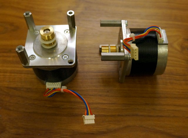
ATMs contain lots of mechanical and electromechanical parts perfect for robots and the like. Maybe the most usable parts I have found are big NEMA 23 stepper motors. In the process of trying one of these steppers out, I burnt both of my two Big Easy Drivers. This setback forced me to try using the undocumented drivers scavenged along with the motors.
Stepper motors
The stepper motors are manufactured by Minebea-Matsushita and are labeled 23LM-C355-50V. A search on Google does not return a exact match but other motors beginning with 23LM-C355 can be found. These motors are both bipolar and unipolar but share some properties; they all operate at 24VDC and have a step angle of 1.8 degrees. The motors I've found have four wires, and therefore, are bipolar. Measurements with a multimeter revealed that the red and yellow wire are connected to one coil, thus blue and orange are connected to the remaining coil.
- 200 steps per revolution
- Bipolar (RED/YEL, BLU/ORA)
- 24VDC

Motor controller
Unable to find any information what so ever about this board, I set out to try and figure out how to use it on my own.

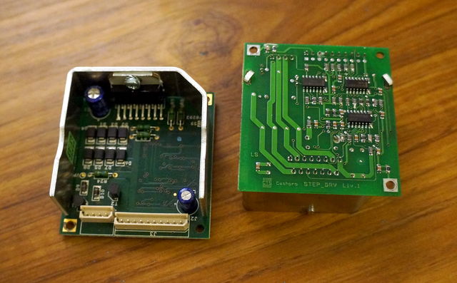
The motor controller boards have the text "Cashpro STEP_DRV Liv.1" or "Cashpro STEP_DRV Liv.2" printed on the back side of the PCB. The large IC attached to the heat sink is a L298N dual H-bridge motor controller. The smaller logic circuits on the back side consists of one 7405 hex inverter, a 7407 hex buffer and one LM339 quad comparator.
Using my multimeter, it was easy to trace the ground to pin 2 and 9, the motor supply to pin 1 and the logic supply to pin 10.
I was only able to trace pin 3 and 4 to two of the four inputs available on the L298N, but since there is one inverter on the board, the remaining two inputs signals can be generated. Pin number 5 is connected to both enable pins on the H-Bridge chip.
I got the motor running in this configuration, but the motor was very easy to stop using my fingers. At that point I started experimenting with the remaining pins by applying 5V to them to see what would happen. When I applied 5V to pin 7, the motor started to sound different and also became impossible to stop with my bare hands—but the controller started to smell warm after a few seconds. Pin number 7 seems to control the current delivered to the motor. After a little trial and error I got the motor running nice without any overheating problems by inserting a 130kΩ resistance between 5V and pin 7.
This information is sufficient to start playing with the motor controller! I don't know what the other pins are doing yet—but it would be cool if one for example could monitor the load on the motor.
Pinout
- Motor VCC
- GND
- Input 1
- Input 2
- Enable (LOW = enabled)
- Unknown
- Current limiting
- Unknown
- GND
- Logic VCC (5VDC)
Arduino Example
To facilitate experiments with the Arduino, I replaced the connector on the controller board with 2.54mm break away headers.
Connections
In addition to the connections in the table below, I connected the stepper controller boards pin 1 to 13.8VDC and pin 2 to GND on my power supply. The motors can handle 24VDC but I was too lazy to dig out my big power supply.
| Adruino pin | Intermediate | Controller pin |
|---|---|---|
| 5 | - | 5 |
| 6 | - | 3 |
| 7 | - | 4 |
| 5V | 130kΩ resistor | 7 |
| GND | - | 9 |
| 5V | - | 10 |
Code
#include <Stepper.h>

const int stepsPerRevolution = 200;
Stepper myStepper(stepsPerRevolution, 6, 7);

void setup() {
  myStepper.setSpeed(120);
  pinMode(5, OUTPUT);
  digitalWrite(5, HIGH); //disable
}

void loop() {
  digitalWrite(5, LOW); //enable
  myStepper.step(stepsPerRevolution);
  digitalWrite(5, HIGH); //disable
  delay(1000);

  digitalWrite(5, LOW); //enable
  myStepper.step(-stepsPerRevolution);
  digitalWrite(5, HIGH); //disable
  delay(1000);
}
The example code is based on Arduinos built in example "stepper_oneRevolution".
Video
Motor and controller in action.
Comments